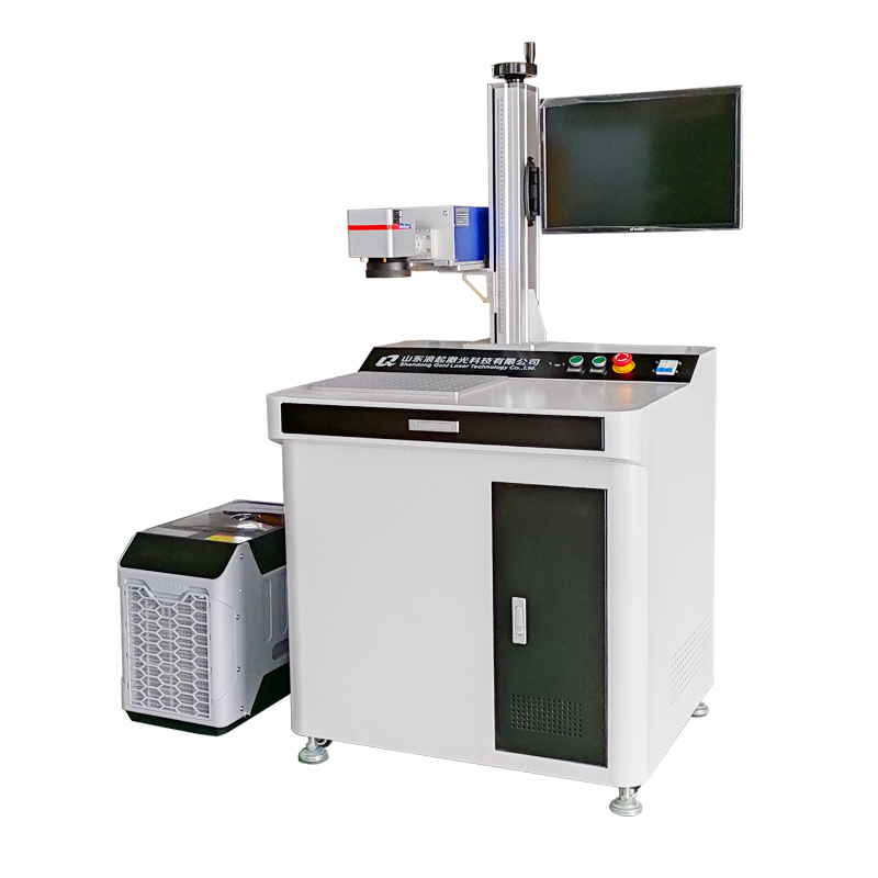
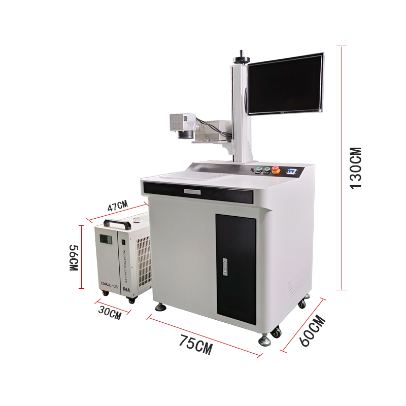
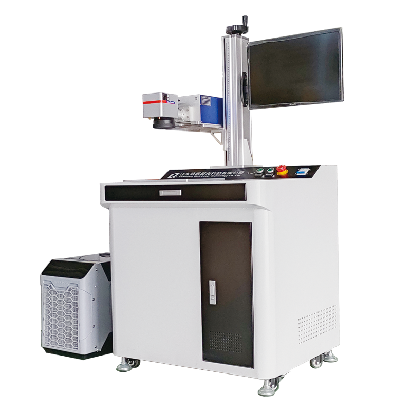
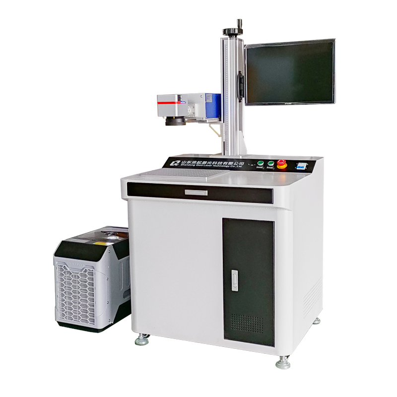
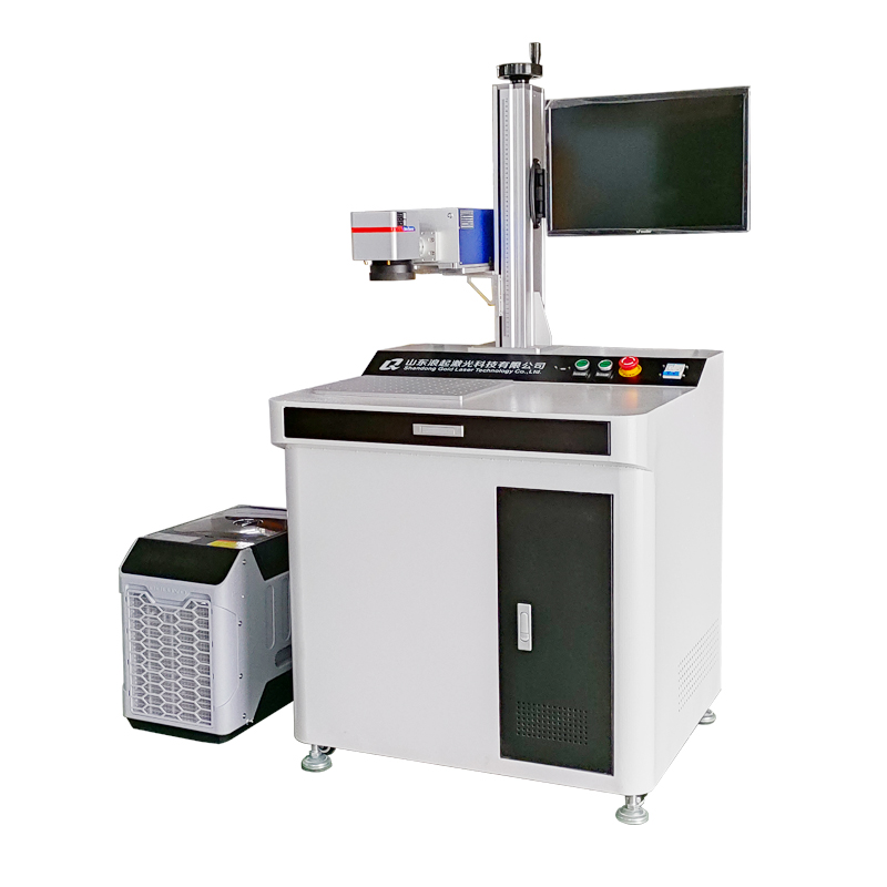
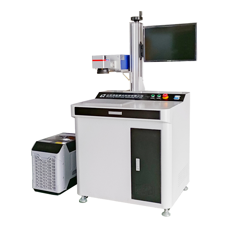
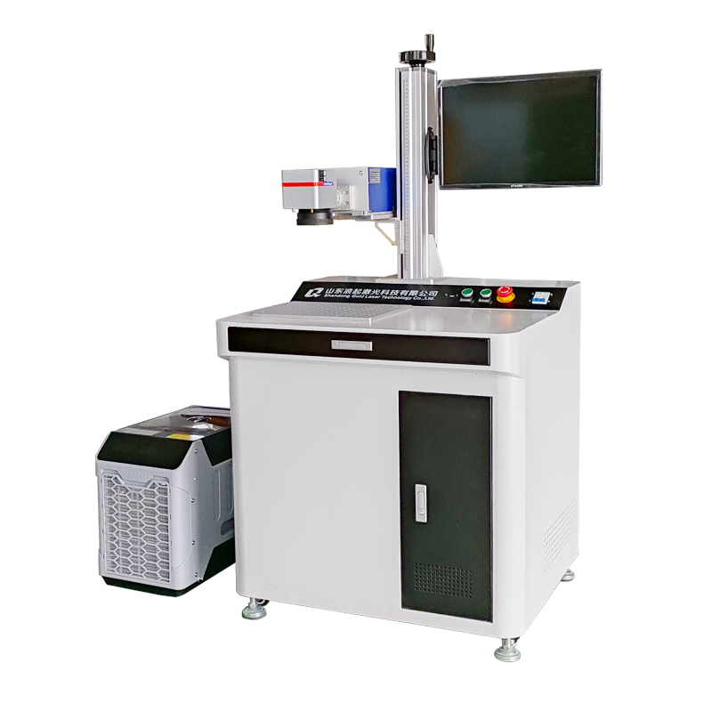
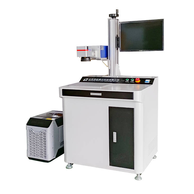
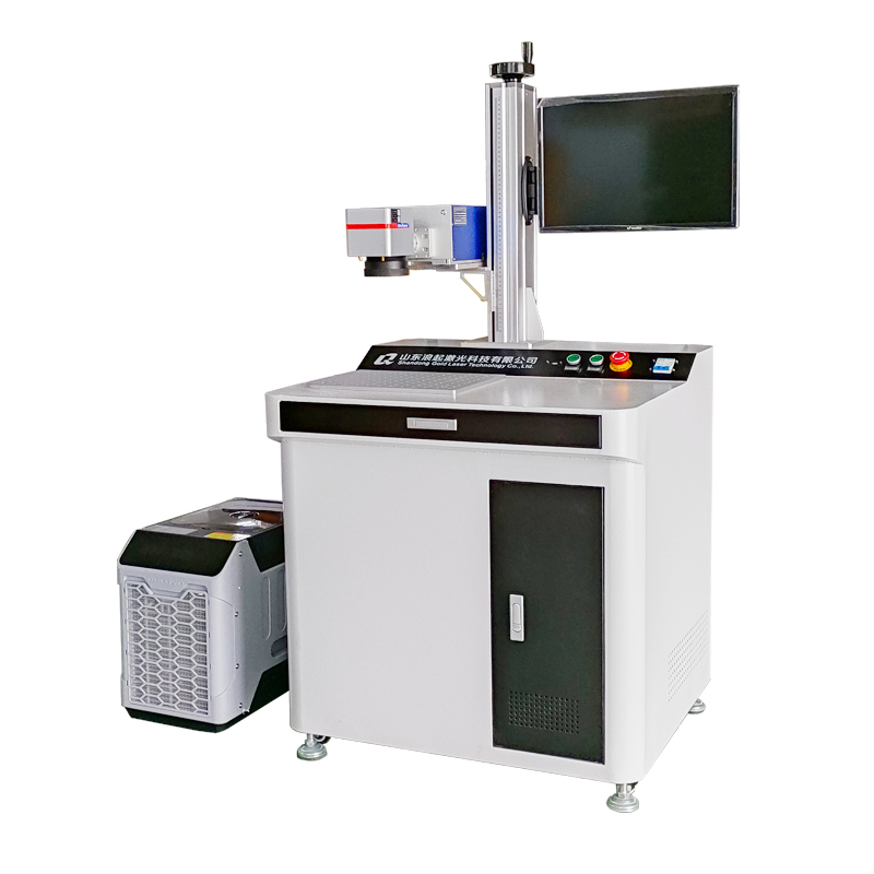
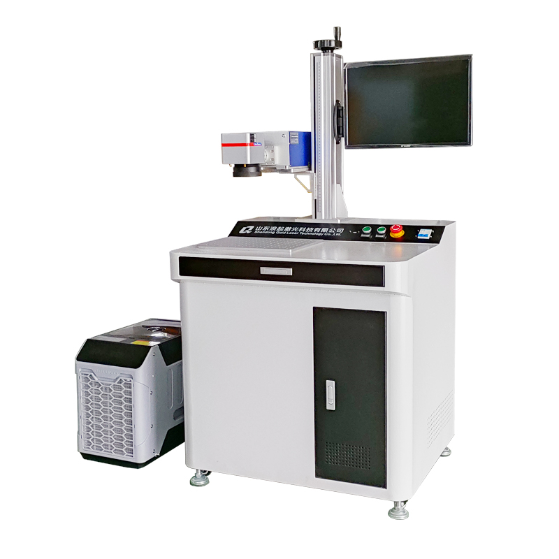
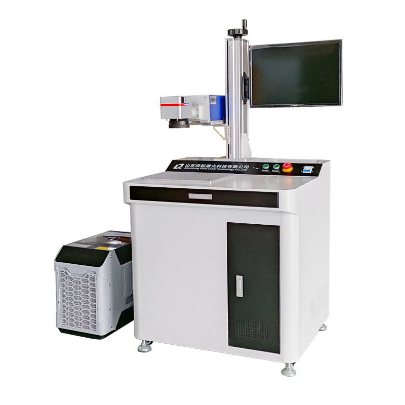
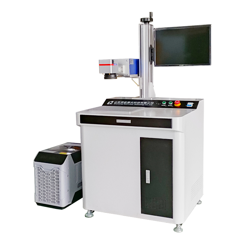
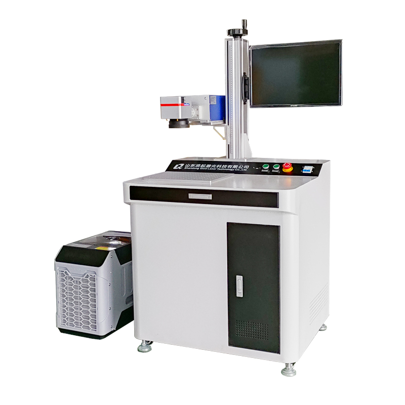
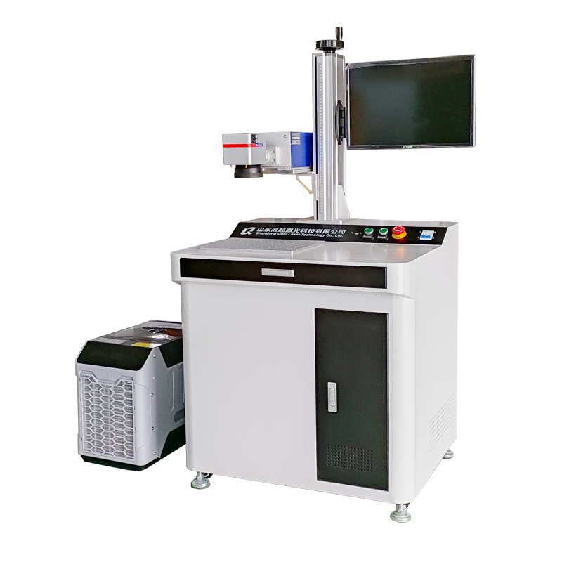
Of course. Marking inside or on the edge of a hole with a UV laser marking machine is a common but technically specific application. It presents unique challenges compared to marking on a flat surface.
Here’s a comprehensive breakdown of the process, challenges, and solutions for using a UV laser marking machine on holes.
Why a UV Laser is Ideal for This Task
UV lasers (typically 355nm wavelength) are excellent for this precision work due to their "cold mark" process:
Minimal Heat-Affected Zone (HAZ): They ablate or alter material without generating significant heat, preventing warping, burning, or thermal stress on the thin edges of the hole.
High Precision: The short wavelength allows for a very small spot size (often 10-20µm), enabling extremely fine details and small fonts, which is crucial for the limited space inside a hole.
Material Versatility: UV lasers can mark a wide variety of materials that are common in parts with holes (e.g., plastics, glass, anodized aluminum, coated metals, circuit boards) with high contrast.
Key Challenges When Marking on Holes
Depth of Field (DoF) Limitation: This is the most critical challenge. A laser beam has a specific focal plane where it is smallest and most powerful. As you move away from this perfect focus (up or down), the beam defocuses, loses power, and the mark becomes wider and fainter.
Problem: The inside surface of a hole is often recessed, placing it outside the laser's limited depth of field. This results in an inconsistent, faint, or incomplete mark.
Accessibility and Collision Risk: The laser head (galvo scanner) must be positioned close to the workpiece to achieve a small spot size. If the hole is deep or recessed, the head or the focusing lens (F-theta lens) might physically collide with the part.
Beam Angle and Distortion: Marking on a curved surface (the inner wall of a hole) can cause distortion, similar to projecting an image onto a curved screen. The edges of the mark may be out of focus or stretched.
Fixturing and Focus Finding: Precisely and consistently positioning the part so that the marking surface is at the focal point for every cycle is essential for repeatability.
Solutions and Best Practices
1. Technical Solutions on the Machine
3-Axis Dynamic Focus System (Often called a "Z-Axis" or "3D" Laser System):
This is the premier solution for this problem. A 3D laser system has a motorized Z-axis that dynamically moves the focusing lens up and down during the marking process.
How it works: The marking software creates a height map of the part (e.g., the flat surface is at one Z-height, and the bottom of the hole is 2mm lower). The laser continuously adjusts its focal point to keep the beam in perfect focus across the entire 3D path, resulting in a crisp, uniform mark on both the flat surface and the recessed hole.
Longer Focal Length Lens:
Standard lenses (e.g., 160mm/254mm) have a short depth of field. Using a longer focal length lens (e.g., 420mm) increases the depth of field, allowing a larger range of depths to remain relatively in focus.
Trade-off: A longer focal length produces a larger minimum spot size, reducing the ultimate resolution and detail you can achieve. It's a balance between depth and fineness.
Beam Expander:
Installing a beam expander before the scanner can also increase the depth of field, similar to using a longer lens.
2. Process and Setup Techniques
Precise Fixturing: Use custom jigs or fixtures to hold the part absolutely consistently. This ensures the hole is in the exact same position for every mark, allowing the laser program to be written once and reused.
Manual Z-Height Adjustment: If you don't have a 3D system, you can manually lower the entire galvo head closer to the bottom of the hole. This places the focal plane inside the hole, but will defocus the mark on the top surface if both need to be marked.
Software Compensation (for curved surfaces): Advanced laser software can distort the intended graphic to compensate for the curvature of the hole, "pre-distorting" it so that it appears correct when projected onto the curved surface.
Parameter Optimization:
Speed: Slow down the marking speed to allow more laser pulses to hit the recessed area, compensating for potential power loss due to defocusing.
Power: Slightly increase the laser power to ensure enough energy reaches the target. Caution: Too much power can cause burning, especially on plastics.
Passes: Use multiple low-power passes instead of one high-power pass to achieve the desired contrast without overheating the material.
Step-by-Step Workflow for Marking a Hole
Secure the Part: Place the part in a custom fixture that holds it firmly and references off a fixed point.
Find Focus: Use the machine's red pointer or a manual focus tool to locate the exact point where the bottom (or side) of the hole will be. For a 3D system, you will teach multiple height points to the software.
Create the Graphic: Design your text, serial number, barcode, or logo in the marking software. Position it precisely over the image of the hole.
Set Parameters: Start with recommended parameters for your material and adjust based on the challenges above (speed, power, passes). For a recessed hole, you will likely need higher power and/or slower speed than for a flat surface.
Test Mark: Run a test on a sample part and inspect the result.
Iterate and Optimize: Adjust parameters and focal height until the mark quality is perfect.
Production: Run the job, periodically checking mark quality.
Summary Table: Challenges vs. Solutions
| Challenge | Primary Solution | Alternative Solution |
|---|---|---|
| Depth of Field (Recessed Hole) | 3-Axis Dynamic Focus System | Longer Focal Length Lens / Beam Expander |
| Physical Collision Risk | Longer Focal Length Lens (lets head stay farther away) | Custom Fixturing to tilt part/head |
| Mark Distortion on Curved Wall | Software Curvature Compensation | Design simpler graphics less prone to distortion |
| Inconsistent Focus | Preciple Fixturing & Auto-Focus | Manual Z-Height Adjustment |
Conclusion:
While marking on holes is challenging, a UV laser marker is the best tool for the job. If this is a high-volume or high-precision requirement, investing in a UV laser system with a 3-axis dynamic focus is highly recommended. It seamlessly solves the core problem of depth of field and unlocks the ability to mark on any 3D surface, not just holes. For less frequent jobs, careful setup with a longer lens and parameter optimization can yield excellent results.

