


This is an excellent and crucial topic in laser marking. The selection of the rotation axis is fundamental to achieving high-quality, efficient, and accurate marks on non-flat or complex surfaces.
Here is a detailed explanation of the selection of the rotation axis for a fiber laser marking machine, covering the principles, types, selection criteria, and applications.
1. The Core Principle: The Field of View (FOV)
Before discussing axes, it's vital to understand the Field of View (FOV) of the galvanometer scanner (the "galvo" head). The laser beam is steered by two mirrors, and at a fixed working distance, they define a flat, square area where the beam can focus perfectly. This is the marking plane.
The Problem: When you need to mark on a curved or cylindrical surface (e.g., a bottle, a pen, a bearing), if you simply place the object under the galvo head, the curvature will cause the surface to fall in and out of the focal plane. This leads to:
Defocusing: The laser spot becomes larger and less powerful, causing inconsistent mark depth, color, or even failure to mark.
Distortion: The intended graphic or text becomes stretched and warped because the distance from the galvo head to different points on the surface varies.
The Solution: A rotation axis (often called a rotary attachment or 4th axis) integrates a motorized chuck or platform that rotates the object synchronously with the movement of the laser galvo mirrors. This effectively "unwraps" the curved surface into a flat, virtual plane that matches the laser's flat FOV.
2. Types of Rotation Axes & Their Selection
There are two primary configurations for a rotary axis. The choice between them depends entirely on the shape and size of the workpiece.
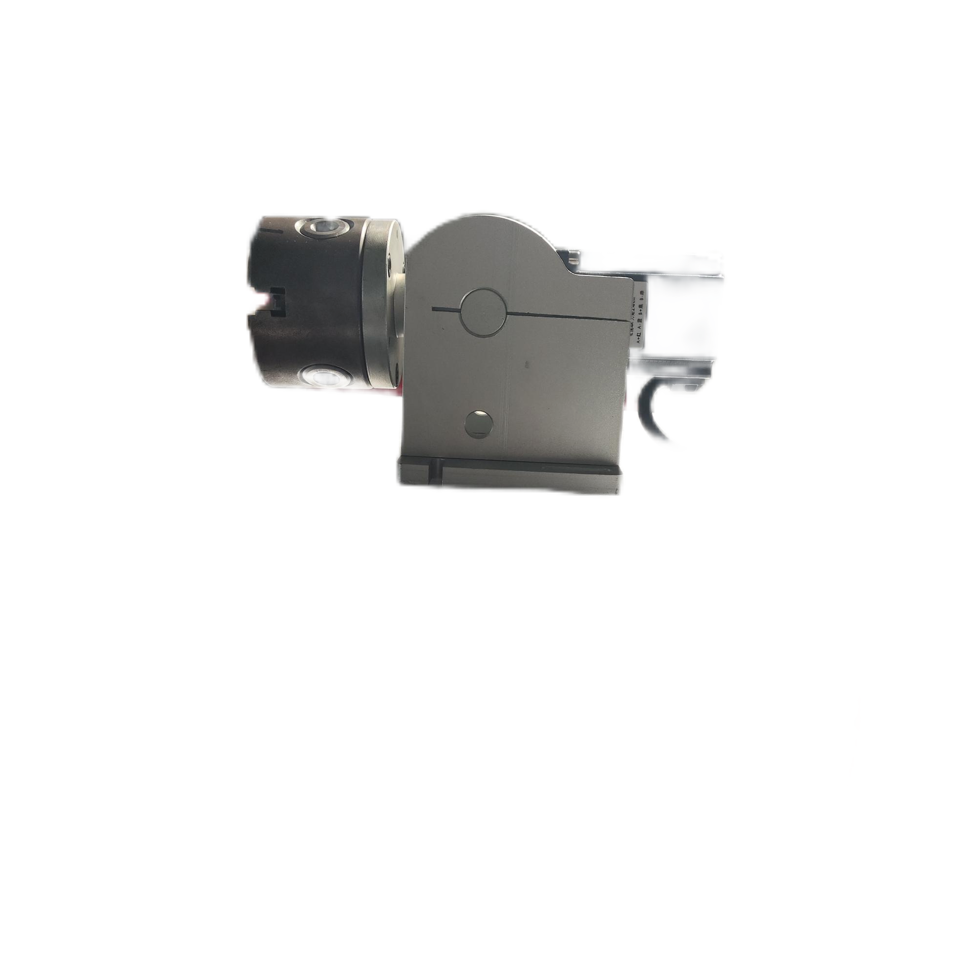
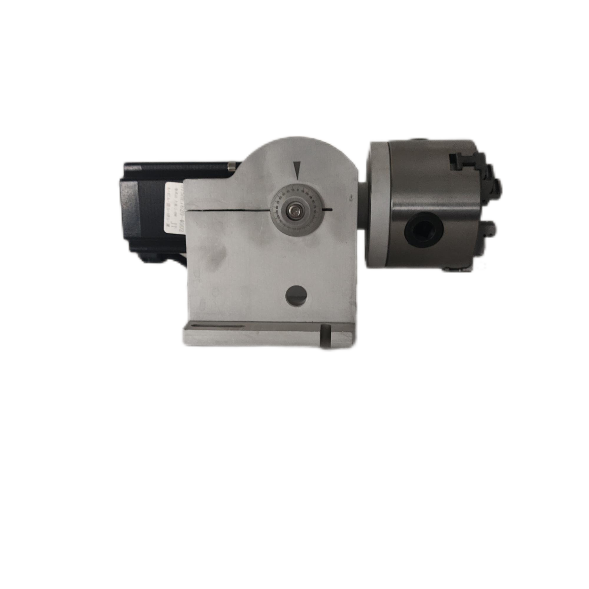
A. Cylindrical (Roll) Axis
This is the most common type. The workpiece is held between two chucks (like a lathe) and rotated.
How it Works: The laser head is positioned directly above the workpiece. As the motor rotates the object, the galvo mirrors move the laser beam along the X-axis (the length of the object). The coordination between the rotational speed (C-axis) and the linear laser movement (X-axis) maps the curved surface onto a flat Cartesian plane in the marking software.
When to Select It:
Cylindrical Objects: Perfect for parts that are fully rotational symmetrical along one axis.
Examples: Pens, bottles, syringes, vials, pipes, shafts, bolts, rings, and bearings.
Key Consideration: The object must have features (like centers) that can be gripped by the chucks.
Diagram Concept:
 Laser Galvo Head
       |
       | (Beam)
       |
[ Chuck ] ======[ Workpiece ]======[ Chuck ]  <--- Rotates (C-axis)
       |
       |
X-axis Movement (via software coordination)
The laser beam moves in X while the part rotates in C, covering the entire surface.
B. Rotary (Yaw) Axis
This type features a motorized platform that rotates the workpiece on a horizontal plane underneath the stationary laser head.
How it Works: The workpiece is placed on a platform that spins. The laser uses its standard X and Y galvo mirrors to mark. This is best for marking on the face or end of a cylindrical part, or on flat circular parts.
When to Select It:
End Faces of Cylinders: Marking on the top of a bottle cap, the end of a pipe, or a flange.
Flat Circular Parts: Marking logos and serial numbers on washers, coins, or discs.
Partial Arcs: Marking on a specific angular segment of a part without a full rotation.
Large/Delicate Parts: For objects that are too large or fragile to be held between chucks (e.g., a large-diameter tube), they can be placed on a platform and rotated.
Diagram Concept:
 Laser Galvo Head
       |
       | (Beam)
       |
[ Rotating Platform ]  <--- Rotates (C-axis)
       |
       |
[ Workpiece ] (e.g., a bottle cap)
The part spins under a stationary laser head, which marks with its X-Y mirrors.
3. Key Selection Criteria and Factors to Consider
Choosing the right axis isn't just about the part shape. You must consider these technical factors:
Part Geometry and Size:
Diameter Range: What is the min and max diameter the rotary chuck can hold?
Length: What is the maximum length of the part that can fit between the chucks (for a cylindrical axis)?
Weight Capacity: Can the rotary stage motor handle the weight of the part without stalling?
Accuracy and Resolution:
The motor must have high enough angular resolution (e.g., number of pulses per revolution) to ensure the mark does not have "stitching" or misalignment errors at the seam where the mark begins and ends. Servo motors are generally more accurate than stepper motors.
Integration with Software:
Translate the 2D design file into coordinated X + C movements.
Precisely set the circumference of the part to prevent distortion.
Allow for easy seam placement and adjustment.
This is critical. The rotary axis must be fully supported and integrated into the laser marking software (e.g., EzCad, LightBurn). The software must be able to:
Mounting and Integration:
How does the rotary axis attach to the main laser machine? Is it a standalone unit that sits inside the cabinet, or is it an external attachment?
Does the machine's Z-axis have enough travel to focus on the part held in the rotary chuck?
Throughput and Automation:
For production lines, consider automated rotaries that can be integrated with feeders, conveyors, and robotic arms for loading/unloading to maximize efficiency.
4. Practical Application Workflow
Design: Create your mark (text, barcode, logo) in the software as if it were for a flat surface.
Select Axis Type: In the software, choose the marking mode: "Rotary" or "Cylindrical".
Input Parameters: Enter the key parameter: the diameter or circumference of the workpiece. This allows the software to calculate the correct scaling for the rotation.
Positioning: Place the workpiece securely in the chucks or on the platform.
Focus: Adjust the laser head's Z-height to bring the surface of the part to the focal point of the lens.
Mark: Execute the job. The software will automatically control both the galvo mirrors and the rotary motor to apply a distortion-free mark.
Summary Table
| Feature | Cylindrical (Roll) Axis | Rotary (Yaw) Axis |
|---|---|---|
| Primary Use | Marking on the side of cylindrical objects. | Marking on the face/end of objects or flat discs. |
| Motion | Part rotates; laser moves linearly (in software). | Part rotates on a platform under a stationary laser. |
| Ideal For | Pens, bottles, tubes, shafts. | Bottle caps, washers, coins, flanges. |
| Key Parameter | Part length and diameter. | Part diameter and height. |
Conclusion:
Selecting the correct rotation axis is not a luxury but a necessity for marking on any non-flat surface. By carefully matching the shape of your workpiece to the type of axis (Cylindrical for sides, Rotary for faces) and ensuring the technical specifications (size, accuracy, software) are met, you can achieve perfect, high-contrast, and legible marks on even the most challenging curved products.