


- 1. Understanding the Components
- 2. Mechanical Adjustment and Setup (The "Adjustment")
- A. Centering and Alignment (Crucial for Chuck Style)
- B. Height Adjustment (Z-axis)
- C. Roller Spacing (For Roller Style)
- 3. Software Configuration and Movement (The "Movement")
- A. Driver and Axis Selection
- B. Calibrating the Movement (Most Important Software Step)
- C. Creating and Positioning the Mark
- 4. Common Troubleshooting & Tips
- Summary Workflow
Of course. This is a critical topic for operators of fiber laser marking machines. The "rotating axis" (or rotary attachment) is what allows you to mark on cylindrical or conical objects like bottles, pens, bearings, or screws.
Here is a comprehensive guide covering the adjustment, movement, and operation of the rotating axis for a fiber laser marking machine.
1. Understanding the Components
A standard rotary axis setup consists of:
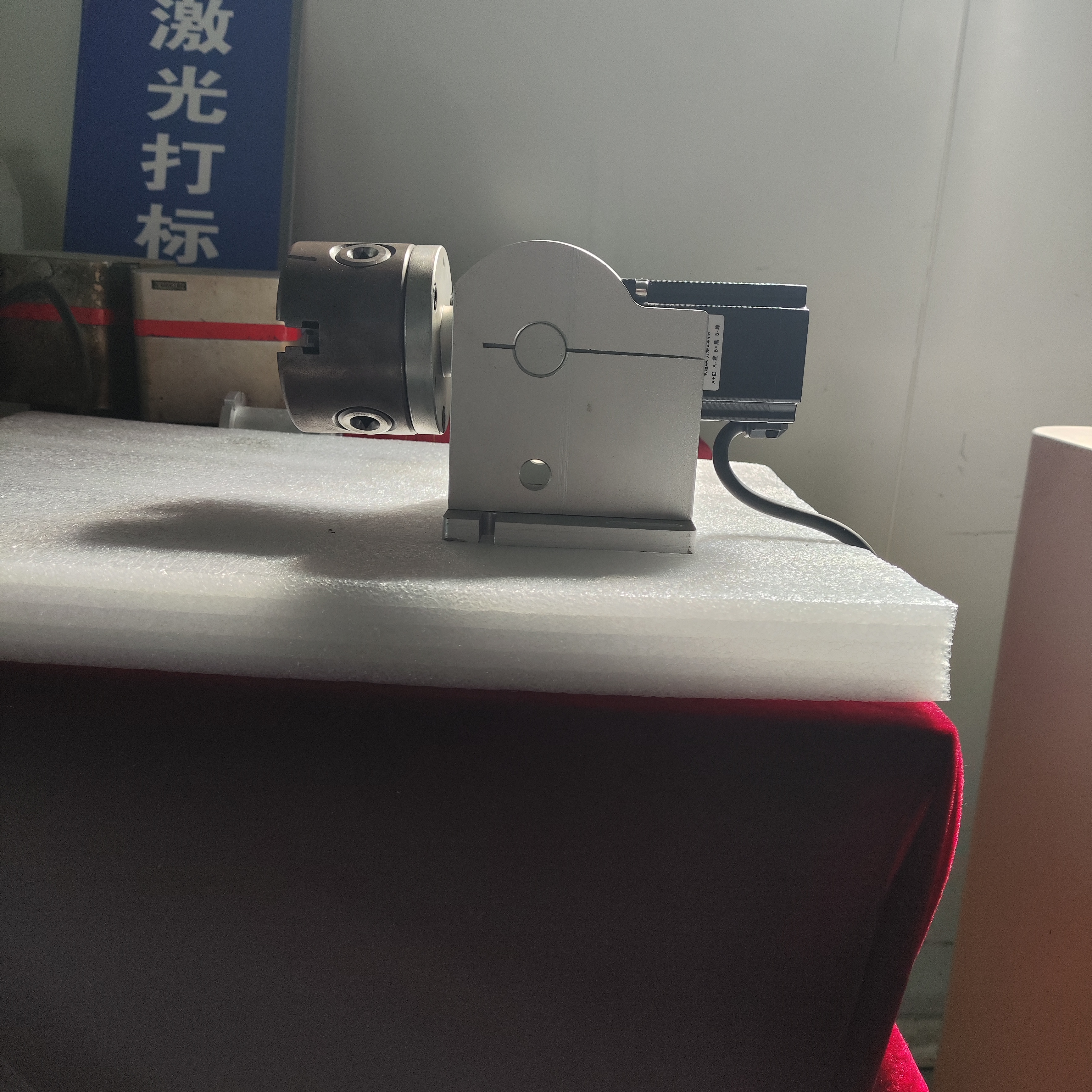
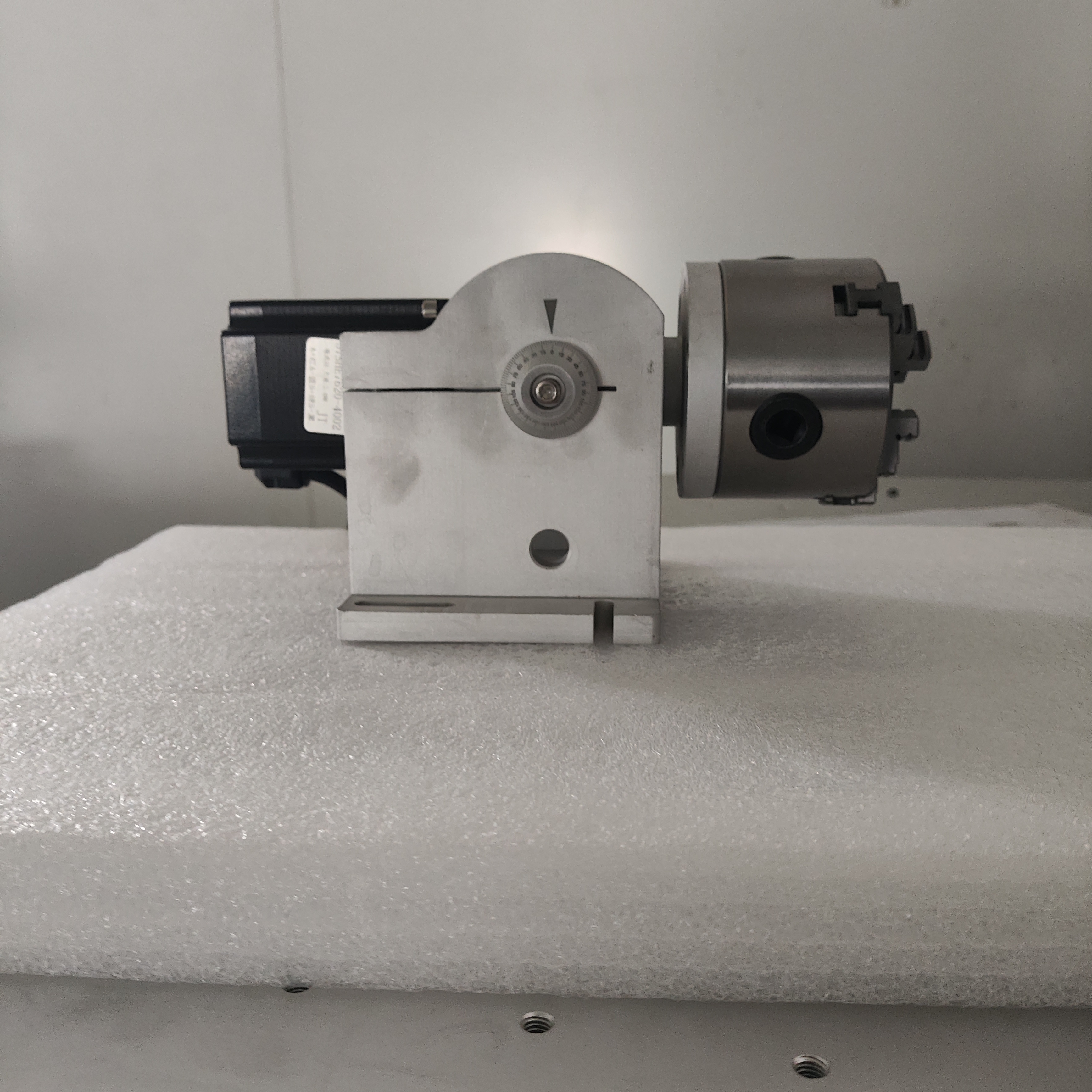
The Rotary Device Itself: This is the motor-driven unit placed inside the laser work area. There are two main types:
Chuck Style (3-Jaw or Collet): Ideal for precise, concentric holding of smaller, rigid objects like pens, bolts, or syringe barrels. It grips the object from one end.
Roller Style (Synchronized Rollers): Uses two or more motorized rollers that the object rests on. Best for long, heavy, or fragile items like bottles, tubes, or cylinders where a chuck cannot be used.
Stepper/Servo Motor: Drives the rotation with high precision.
Controller/Driver: This can be integrated into the main laser controller or be a separate box. It receives signals from the laser software to control the rotation speed and angle.
Software Integration: The laser marking software (e.g., EZCAD2, which is very common) has specific functions and drivers to control the rotary axis.
2. Mechanical Adjustment and Setup (The "Adjustment")
This is the physical setup to ensure the object rotates perfectly and the mark is aligned.
A. Centering and Alignment (Crucial for Chuck Style)
Mount the Object: Securely place your object (e.g., a pen) into the chuck. Tighten the jaws evenly.
Find the Center (Runout Check): This is the most important step. Use a dial indicator if you have one.
Gently rotate the chuck by hand.
Watch the tip of the object. If it "wobbles," it means the object is not centered on the rotational axis.
Adjustment: Loosen the chuck slightly, tap the object to re-position it, and re-tighten. Repeat until the runout (wobble) is minimized. Poor centering will cause the mark to distort and blur.
B. Height Adjustment (Z-axis)
Laser Focal Length: The laser beam has a specific focal point where it is sharpest and most powerful.
Adjustment: Use the manual handwheel or motorized control on the laser head to raise or lower the entire head until the object's surface is at the laser's focal point. For a rotary, you are setting the focus for the top dead center of the cylinder.
C. Roller Spacing (For Roller Style)
Fit the Object: Adjust the distance between the two rollers so your object (e.g., a water bottle) sits snugly but not too tight.
Alignment: Ensure the rollers are parallel. The object should rotate smoothly without "walking" sideways along the rollers.
3. Software Configuration and Movement (The "Movement")
This is where you tell the machine how to move and mark.
A. Driver and Axis Selection
Install Driver: Ensure the correct driver for your specific rotary model is installed in the laser software (e.g., in EZCAD2's
Fiber->Rotarymenu).Select Axis Type: You must tell the software which axis the rotary is mapped to. It's almost always configured as the X-axis or a dedicated R-axis (Rotary).
X-axis Mapping: The software treats the circumference of your object as a flat, linear X-axis. A 100mm movement in X would correspond to a rotation that moves the laser spot 100mm along the surface.
B. Calibrating the Movement (Most Important Software Step)
You must calibrate the software so it knows how many motor steps equal one full rotation of your specific object.
The "Circumference Method" (Most Common):
Measure the Object: Precisely measure the diameter (D) of your object at the point where it will be marked.
Calculate Circumference:
Circumference (C) = π * DSoftware Calibration:
In EZCAD2, go to
Fiber->Rotary->Calibrate.It will ask for a "Length to Mark." Enter the calculated Circumference (C).
The software will then rotate the object exactly one full revolution.
You now measure the actual linear distance the laser mark traveled along the surface. If it's perfect, you confirm. If not, you adjust the value until one software-unit of movement equals one real-millimeter of travel on the cylinder's surface.
C. Creating and Positioning the Mark
Design Your Graphic/Text: Create your mark in the software as if it were for a flat surface.
Use "Rotary" Text Function: Many software packages have a special "Rotary Text" function that automatically curves the text to fit the cylinder, preventing distortion.
Set Marking Parameters: Adjust speed, power, frequency, etc., as you would for a flat mark. You may need to slightly reduce speed for a clean mark on a moving surface.
Test and Adjust Position: Use the software's "Red Light" preview (which simulates the marking path without firing the laser) to see where the mark will be placed. Use the software's X/Y offset controls to nudge the mark into the perfect position on the object.
4. Common Troubleshooting & Tips
| Problem | Probable Cause | Solution |
|---|---|---|
| Blurred or Distorted Mark | 1. Object not centered (wobble). 2. Incorrect focal point. 3. Rotation speed too high. | 1. Re-center the object in the chuck. 2. Re-focus the laser head. 3. Reduce the rotary speed in the software. |
| Mark Doesn't Join Up (Gap) | Incorrect circumference calibration. | Re-calibrate the rotary axis using the circumference method. |
| Mark is Stretched/Compressed | Wrong axis mapping or calibration. | Ensure the rotary is mapped to the X-axis and that the calibration is correct. |
| Object Doesn't Rotate | 1. Software not set to "Rotary" mode. 2. Loose cable connection. 3. Motor driver fault. | 1. Check the software rotary settings. 2. Check all cables. 3. Consult machine manual/service. |
| Mark is in Wrong Location | Incorrect X/Y offsets in the software. | Use the red light preview and adjust the object position or software offsets. |
Summary Workflow
Physically Mount: Secure the object in the chuck or on the rollers.
Center & Align: Minimize wobble.
Focus: Adjust laser head height.
Software Setup: Select the correct rotary driver and axis (usually X).
Calibrate: Use the circumference method for accurate movement.
Design & Position: Create your graphic and use the red light to position it.
Test & Mark: Run a test on a sample piece and fine-tune power/speed before the final mark.
By following these steps, you can reliably adjust and control the rotating axis of your fiber laser marking machine to produce high-quality, permanent marks on cylindrical objects. Always refer to your specific machine's manual for details on its proprietary software and hardware